Game Level Design II 2

Now, that we've our little house, we can start to "build around". To make things much more easier while modelling, moving or texturing objects, we'll use "round" values as much as possible, making the Blender "snap" function ( and the " Transform Properties" floating panel) a very useful tool.
Select the house object, press "N" key to make the "Transform Properties" panel appear in the "3D" view, enable "Link Scale", set the "Scale X:" value to "5.000" and the "Loc Z:" one to "5.000" too. Your scene should look, more or less, like the one in the image above!
Why these values? Well, after the creator of the "Bullet Physics Engine" used by Blender's "Game Engine", the physics engine will try to simulate, more or less, the "real life" ones. So, to stay in tune with "real life" measures, when adding a standard cube to our scene ( black shape in the image above, that measures "1 blender unit"), this means, that the cube measures "1 meter", therefore our little house will measure 5 meters ( tall, wide and large).

Now we'll create the central square of our village, with a nice pavement, like the one in the image above. The pavement area will measure 40x30 meters.
A cool task? A basic plane with some mapped image texture? Don't underestimated it, sometimes, easy looking objects like this one, could be quite tricky to achieve.
A little planning will be needed!
We could, indeed, use a single texture "UV Mapped" directly to this single face/poly object, but due to the size of it, it'll look quite ugly, once used in the game engine. Instead, we'll divide the plane where the pavement pattern is more detailed.
Analyzing the pavement drawing ( image above), we can notice that most of his surface its covered with tiled paving stones ( red area), that the four corners are equal ( green areas), and that the same pattern is used along the four sides ( blue areas).
We'll need three different textures.

Open your favorite image manipulation program ( "The Gimp" of course!), create a new big document ( at least 1024x1024), place one vertical and one horizontal ruler at the middle of the image, make the paving stones with the "Distortion-Mosaic" filter, make the texture "tileable" with the "Resynthesize" one ( if installed), then re-size the layer with the "Scale" tool to the top left image quarter, do "Layer-Layer to image size", select the first quarter, using the rulers, and place copies in the other three ones! Add some repeating graphic patterns, to the top and left sides, and at the end, you should have something, more or less, as in the image above.
Finally, we've our three textures, the "4" being the same as the "2" we can discard it.
Flatten your image (carefully), cut each quarter in a new image, re-size each one to "256x256pixels", apply some "sharp" filter, maybe, and save as "jpg" format with "0.85" compression.

Now, we gonna model the object that will use those textures, the square.
With the "3D" cursor still placed at the center of the scene ( x, y, z:0.000), add a plane with size "X:30" and size "Y:20".
Enter "Edit mode", select the two top vertices, press "E" key to extrude them, choose "Only Edges" in the "pop-up menu", "middle-mouse button" click, while moving towards the top to enable the "Y axis constraint", a "light green" line will appear, and then, while pressing the "Ctrl" key ( snap to grid), check the the "D:" values in the "3D window" header. Stop when reaching "10.00". Do the same for the opposite two vertices ( "1" in the image above).
Repeat the previous step, but, now, with the four left side ones and then the four right side ones ( "2" in the image above).
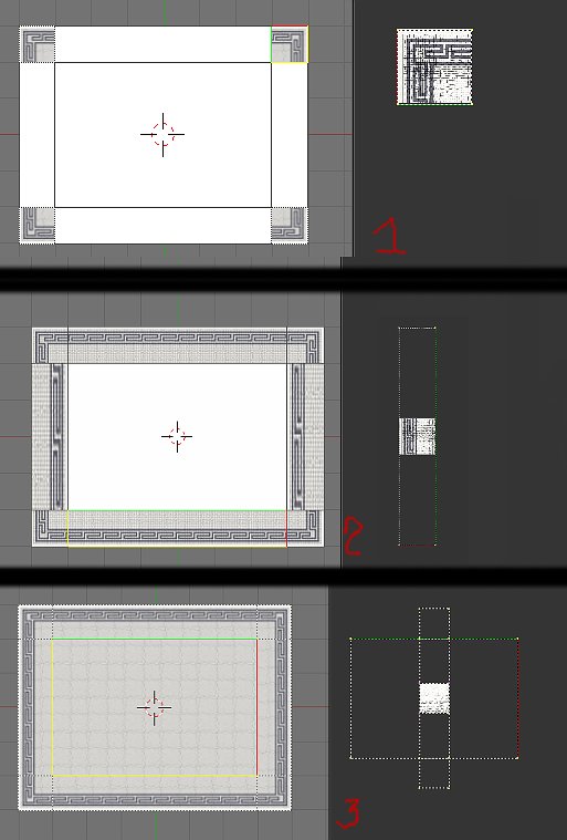
We'll apply the textures to the object, now. In "Object mode", do "F" key to enter "UV Face Select mode", select the four corners faces and in the "UV Editor", load the "passeio-corner.jpg" image ( or one of your own). Most probably, some of the corners texture will be positioned in wrong direction, that you can adjust, selecting each face at a time, and rotate the "UV Co-ordinates", with "R" key ( "1" in the image above).
Now, select the four sides faces, load the "passeio-side.jpg" image, and, again, rotate the "UV Co-ordinates" where needed, but, this time, scaling the "UV" faces will be necessary.
The first time you enter "UV Face Select mode" for an object, if you select all faces, you can observe, in the "UV Editor", that all the vertices/faces ( quads or tris), fit perfectly the "active square area" outline. It's the "default" state, and quite useful.
So, using the "3D window background, dark grey guidelines" you can see that the vertical sides measure "4 squares by 1", and the horizontal ones, measure "6 squares, by 1. Apply this counting to the vertices of each face ( select face, select all vertices in "UV Editor", use "Y axis constraint-/Ctrl key" to scale/snap, and survey the "Scale:" value in the header, "4.00" for vertical sides, and "6.00" for horizontal ones ( "2").
Repeat this for the central face, with "passeio-tile.jpg" image, scaled "4.00" in the "Y axis" and "6.00" in the "X" one ("3").
To finish the object, enter "Edit mode", select the twelve outline vertices, extrude them down by "0.200", select all the new faces, switch to "UV Face Select mode", the faces should be already selected in the "UV Editor", and scale them to fit in the white area in the left side ( pavement border).

Here's our new scene in "Game mode" ( image above).